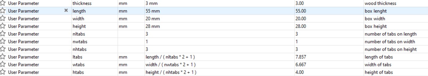
Edit certain specification like height,length, weight and thickness to desire parameter
Front Plate
Create new component, name "Front plate"
Create sketch on the ZX plane
Create a rectangle with dimension of "length" and "height"(dimension use follow parameter)
Extrude the image with distance of "thickness"
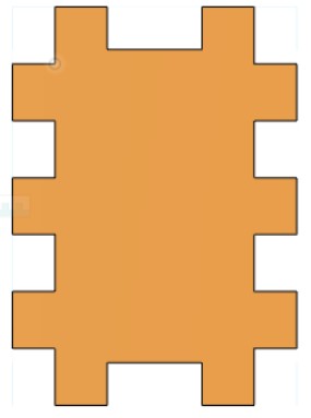
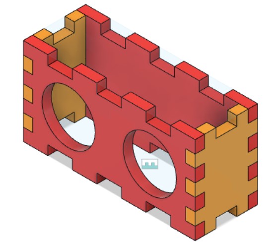
Next, create tabs on both sides and bottom, create rectangle(whixh is the tabs),dimension using the parameter(length of tabs on width is wtabs or length of tabs on height is htabs) by thickness
Extrude cut the tabs with dimension: thickness
Using rectangular pattern, enter the number as parameter(nltabs or nwtabs) and distance is (length - length of tab*3) or (width - width of tabs*3)depends on which dimensions use to refer
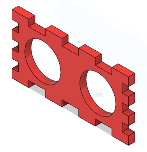
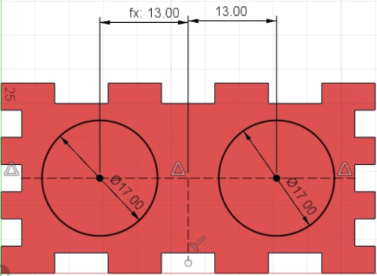
Create a sketch on the plate and make construction line on the midpoint and constuct circle with diameter 17mm, 13mm away from midpoint and mirror the circle to extrude cut.
Side Plate
Create a new component on the right face of the front plate
Create rectangle and colinear to constraint the side and dimension the width
Using same setting on desgin front, similar steps, add tabs but now only do on the width, or bottom face of the right plate will do
Extrude and rectangular pattern to form the tabs
Mirror Plate
Create midplane on both component, mirror both components(front and side plate) (for mirror front, no need to mirror the holes created)
Combine cut all the plates at side in order to create joins.
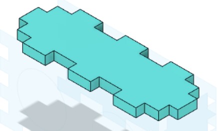
Cover (TOP)
Create component for making a cover on the top surface of either front or side component
Create a rectangle and extrude with a dimension of "thicknes"(parameter)
Combine the cover using all other 4 plates as cutting tool to cut the cover.