Welcome to Laptop Stand design Current Time:


LAPTOP STAND


5

Leg Support

  • Measure a suitable height to place the computer, create a support design as below
  • After contraint all sketches and before extrude, go to "Modify" > "Change Parameter"
  • To summarise, parameters allows edit on the extrude distance without using edit feature or extrude, which is easier to change the thickness of certain bodies or component
  • When extrude, instead of entering distance(thickness), enter "legwidth"(according to the name given in parameter)
  • After extrude, copy paste this component to same design, remember not to move the copied component.
  • Next, use "join" function, hide leg support 2, choose one side of the support as one reference point, unhide support 2 and hide support 1, choose oppositeface(side)
  • Along Z-axis distance, instead of distance entered, use defined parameter name("legdistance" in this case)
  • Table board( Top )

  • Create new component, name top(to place computer)
  • Create sketch on the slanted surface instead of horizontal
  • Use "Create > "Project include, include another face
  • Create rectangle and colinear to the side(so when the legsupport distance increase, this component will increase also)
  • Use contruction line contraint to all midpoint of rectangle
  • Next create rectangle(act as join), which width is colinear to the width of leg support
  • Mirror the small rectangle(join) using the the contruction line as reference point
  • Extrude inwards the rectangle other than the small rectangle(not cut but new body), distance follow("legwidth" instead distance)
  • Next,"modify" tool > "combine" tool
  • Target body is the one need to be modified, Tool body is the one to make as reference(check the keep tools so will not loose the part)
  • Hide the top board or tool body to see the changes made
  • Bottom Support

  • Using the support as reference, offset plane from it using parameter or distance
  • Create sketch on that plan, create a rectangular and colinear contraint similar to previous steps
  • Sketch one line across the midpoint of rectangle
  • Extrude symmetric the designated sketches, except for small rectangle(join) to create the support (distance use legwidth parameter)
  • Next, use midplane to create a plane, use front and back plane of side support as reference
  • Mirror the created bottom support using midplane as reference, and modify using similar steps mentioned
  • Lastly fillet or chamfer the corners
  • Laptop Stand:

    Animation

  • Under Design Tab, choose Animation
  • To move a component, select it and press transform, which is similar to move tool. Once it is move, it will be shown on the timeline where can adjust the duration
  • There is also auto explode which fusion 360 will automatically explode the components
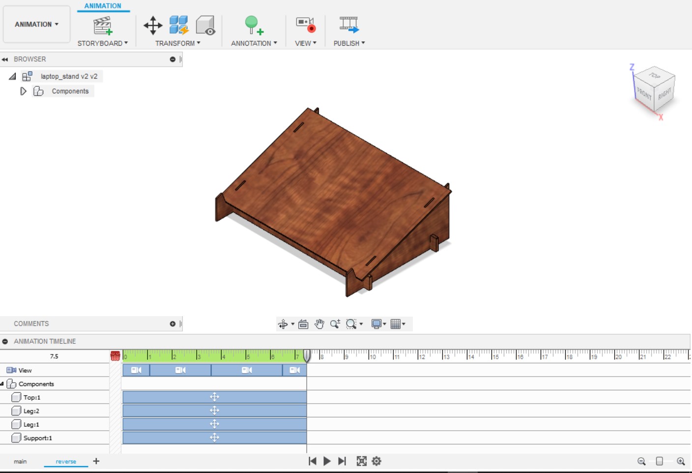
  • When complete, there is a publish tool which can create a video of own model with animation move edited by ourself
  • Upload it to youtube and people are able to view your video
  • Own video about laptop stand

    Learn More